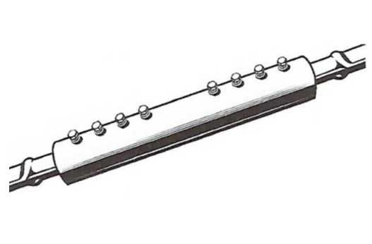
Screw Couplers
Screw Couplers
Mechanical Splice Requirement
This type of mechanical splice consists of a coupling sleeve with shearhead screws which are designed to shear off at a specified torgue. The reinforcing bars are inserted to meet at a stop at the center of the coupling sleeve and the screws are tightened. The tightening process embeds the pointed screws into the bars. For one type of splice, the screws force the bars into contact with internal gripping rails. For the other type of splice, the screws force the bars to wedge into the coupling sleeve’s converging interior wall. The heads of the screws can be tightened using pheumatic impact wrench. For making a splice between two fixed bars, coupling sleevs without a center stop are available. This sleeve can be slipped ocmpletely onto one bar and subsequenty repositioned over the two bar ends.
ACI 318 Chapters 18 and 25 state the requirements for mechanical splices. They are:
TYPE 1
Shall develop in tnsion and compression as required at least 125 percent of the specifiedf yeild of the bar. Example: For ASTM A615 grade 60 bar: 1.25 x 60,000 psi = 75,000 psi. Therefore, a splice test exceeding 75,000 psi meets the Type 1 requirement for A615 Grade 60 bar.
TYPE 2
Shall conform to Type 1 requirements and develop 100% of the specified ultimate strength of the bar being spliced. Example: For ASTM A615 Grade 60 bar: 1.00 x 90,000 psi = 90,000 psi. Therefore, a splice test exceeding 90,000 psi meets the Type 1 and Type 2 requirement for A615 Grade 60 bar.
GRADE 80
Call for specific information.


